When designing a structure or a building, coming up with different drawings is mandatory. In this respect, plan section elevation drawings are among the most common ones you will encounter as an architect. Usually, they contain lots of crucial information and characteristics about a building, and architects refer to them while working on a project.
That’s why it’s important to understand what each drawing is all about. Do you have trouble understanding what the plan, section, and elevation drawings are all about? Keep reading.
What Is a Plan Drawing?
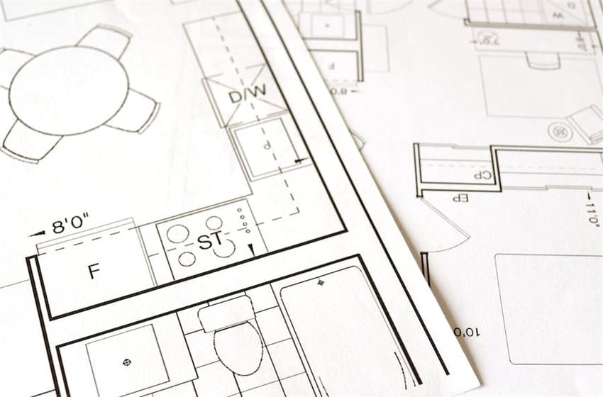
A plan drawing is a two-dimensional representation of a structure that visually displays its design in a horizontal view. In other words, it is a bird’s-eye view of a structure. For instance, when sketching a floor plan, you need to remove the roof from your drawing so that you can see the layout and interior from above. It provides detailed information about the dimensions, shape, and purpose of elements such as walls, windows, and doors. In addition to this, these plans also include architectural details such as ceiling heights or room names.
Plan drawings can depict single or multiple views according to the complexity of building project requirements. A plan drawing is the primary representation that an architect uses to demonstrate the relationship of the project components with the structure or building. Different types of plans include:
- Plan Drawings
As we have seen, plan drawings, also known as architecture plans, provide a bird’s eye view of a structure. They are usually used to show the layout of a building, illustrating locations of windows, walls, rooms, stairs, and so on. In most cases, architects draw these plans cutting through the structure on a horizontal plane at a height of 4 feet above the ground. However, they can also opt to cut them at different elevations.
- Plan Callouts
A plan callout is a section of a plan drawn at a larger scale. So, for example, a floor plan of a house at 1/4″ = 1′-0″ could have a callout section of the living room and kitchen illustrating them at ½” = 1’-0″ scale. In this case, the ½ “scale is double the ¼” scale.
- Plan Details
When it comes to architectural drawings, plan details are usually scale drawings that provide information on how the construction process will occur. They are normally ¾” = 1’-0″ or larger. Also, they indicate all the materials and how they connect during a construction project.
- Site Plan
This drawing demonstrates the structure in relation to the whole site where the building sits. A site plan shows the location, power lines, roads, and so on. Architects often draw site plans with a top-down perspective of the structure, as if showing a roof plan of the building within it.
- Roof Plan
It is a bird’s-eye view illustrating the roof layout, stair bulkheads, and parapets. It should also include everything that will go on top of the building, including the solar panels.
- Plan Perspective
It’s an architecture sketch illustrated in perspective. A planning perspective is a design sketch crafted to show how a space will appear without giving information on its creation process.
- Reflected Ceiling Plan (RCP)
It is a representation of a building ceiling within a room or space. Usually, architects draw RCP looking downwards.
Section Drawing Definition
The section plan of a house is a vertical cut through a structure showing the internal features. It is similar to the elevation plan. This type of drawing can help visualize the inner setup of a building without needing to actually segment it. Usually, architects draw section plans in the middle of a structure’s staircase. A section drawing can help an architect and engineers get a clue about the internal floor height of a building and the features present on the walls.
The drawn line appearing within the section denotes the cut line. The position of a cut line matters a lot since it shows useful details about the space it is cutting through. Technically, architects use two-section cuts at right angles, helping the reader see the area from both directions. The cut line in the floor plan is clearly marked, indicating the specific direction in which the section is looking. The marker on the drawing includes both the drawing number of the section and the layout sheet, ensuring easy access to the information.
Just like plan drawings, there are various types of section drawings. They are:
- Section Drawing
A section drawing is like a cut-through picture that helps us see details inside a room. Depending on the details you want to show, you can cut it from any part of the building.
- Section Callout
These are like rectangle shapes with dotted lines, a bubble, and a number. They inform the construction team that there’s more information about a certain part of the project on another drawing.
- Reflected Ceiling Plan
This drawing is like looking at the ceiling as if reflected on a mirror on the floor below. It helps us see things like the structure and how high the ceiling is.
Understanding Elevation Drawing
Those looking at the ceiling show what a building or part of a building looks like. It can be both internal, like a wall in a living room, or external, like a structure’s facade. It’s like taking a picture of the front or inside of a building while standing right in front of it.
These drawings are a usual way for architects and engineers to show how a building will look. You can use line weights and shading to show the depth. Simply put, it’s like looking at the building straight on, without any fancy angles. Types of elevation drawings include:
- Elevation Drawing
An elevation drawing is usually a 2D representation of a structure’s facade. It usually shows the length, height, width, and the main features of a building in relation to a specific point, like natural ground level. Usually, architects draw elevation drawings as if looking at a building from the side or front.
- Interior Elevation
It’s a vertical projection of a surface or wall inside a building. The interior elevation shows all the height details inside a house, from the floor to the ceiling. They include details like the height of doors, walls, fireplaces, bookcases, and so on.
- Elevation Call Out
It’s a short string of messages linked by an arrow to a featured drawing giving details about it.
- Elevation Detail
This kind of drawing illustrates the lower floors of a structure drawn from the curb level to a height of at least 30 feet. Elevation detail includes windows, doors, and signage dimensions.
Importance of Plan, Section, and Elevation Drawings
Drawing plan section elevation is essential to architecture as it offers a comprehensive visual representation of a structure or a building. Through plan drawings, one can create two-dimensional overviews that display information on different levels and walls within a building.
Sectional drawings provide data regarding the interior structures and features that one can’t see through the exterior view. They draw attention to specific details, such as windows, columns, or any other architectural elements that may not be evident from overhead plans. Section plans help stakeholders know more about the structure’s inner workings.

Elevation drawings take an axial approach, providing insight into features such as ceiling heights or window dimensions in addition to several critical detailed illustrations. All three types of drawings are invaluable tools for architects as they help establish a line of communication between all the professionals and workers throughout the project cycle. They provide an understanding of what the building is supposed to look like, thus minimizing mistakes.
Conclusion
As an architect, you must understand the basic principles of architectural drawings. Accurately representing the plan with elevation and section designs on paper is critical. It provides insight into how properly constructed a building will be in the long run. Therefore, these drawings are essential tools for anyone seeking success in their endeavor.